|
|
|||||||||


BUDAPEST METRO LINE 4 FEASIBILITY STUDY Oktober 1996 |
 |
|
POWER SUPPLY |
||||||
Overall description of the power supply equipment
The power supply network for Budapest Metro Line 4 is assumed
to be a private network, no other consumers should be connected
to. The units supplying electrical power for operational needs
and traction are connected to the overall Budapest City system
of electric energy distribution. The voltage at the City feeder
connection will be 10 kV.
The metro power supply network consists of two sub-networks:
the "traction" sub-network, which transforms the 10 kV voltage into 750 V DC by means of rectifier stations (RS) and which distributes this 750 V voltage for power supply of the trains;
the "lighting & power" sub-network,
which transforms the 10 kV voltage into 380/220 V voltage by means
of lighting & power stations (LPS) and which distributes this
380/220 V AC voltage to supply fixed equipment installed in the
stations and the tunnel.
Such an architecture participates in achieving the
reliability and safety that is expected for a metro line most
of which is operated underground. The pursuit of reliability and safety leads to adopt the "active reserve" principle (described at § 2.3.1.), in which the failure of any one of the electrical equipment units does not lead to any disturbance or any need for intervention by the power network operators. Description of the medium voltage feeding network
Separate rooms for the BEM (Budapest Electricity
Company) should be constructed to receive the feeder cables coming
from the City energy distribution network, and to install the
associated switch gears and the meter devices for the electric
energy consumed recording. These rooms should be easily accessible
from public areas.
The rectifier stations (RS) and the lighting &
power stations (LPS) are supplied by two 10 kV cables coming
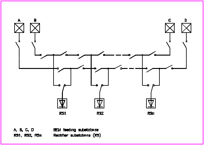
from the BEM input rooms. According to the number of BEM feeding points, the diagram of the medium voltage
network could be as described in the below Figure C-15.
Switches remote-controlled from the power control
system (PCS) are capable of isolate a defective section of each
cable and to send to the PCS a remote signalling information issued
by the homopolar relays.
The medium voltage supply and distribution network
is controlled and monitored from the power control system (PCS).
The PCS, installed in the CCR, controls directly
the various 10 kV breaking devices, notably the traction and lighting
input circuit-breakers, causing automatic start-up of the RSs
and LPSs. The PCS can also control and monitor the remote-controlled 10 kV switches installed in the LPSs. The traction sub-networkGenerality
The traction sub-network is supplied with 750 V direct
current, by substations also called "rectifier stations"
(RS).
These RSs, specific to Metro line 4, cannot supply
any other line either directly or indirectly. Accordingly, an
incident will only affect the line where it takes place.
These RSs are distributed all along the line so as
to be evenly loaded and so that the line cannot be subjected to
voltages unacceptable to the rolling stock in the event of shutdown
of an RS.
In order to accommodate these load carry-overs instantaneously
during degraded situations, the RSs are sized so as to accept
a 50% power overload respect to their normal load ("active
reserve" principle).
Standard IEC 146 recommends that transformer-rectifier
set manufacturers size this equipment so that it withstands 50%
rated power overload for 2 hours. The longest traffic peak period
in Metro line 4 lasts less than 2 hours. In these conditions,
the shutdown of any RS along the line does not lead to any disturbance
in the line - even momentarily - and does not require any operation
performance reduction.
A preliminary sizing using the MARCADET simulation
software with the available data (horizontal and vertical profiles,
as defined at the present stage, preliminary rolling stock characteristics,
assumed running and third rails of UIC 54 and STR 40
type respectively and 90 s theoretical headway as long term
operation performance) leads to a power absorbed by the trains
of the order of 13 MW, of which 4 MW could be regenerated
by the trains. The simulation shows that at this preliminary stage, 8 RSs with a nominal power of 2250 kW (with In / 1.5 In / 3 In - 1 Min characteristics) could be sufficient, complying with the "active reserve" principle, to supply the required energy to the whole Budaörs-Keleti alignment, 6 RSs are required to supply the energy to Kelenföld-Keleti alignment and 4 would be sufficient for Kelenföld-Kálvin section. Rectifier station (RS)
The rectifier stations should be located either in
buildings erected near the line or in specific rooms at the station
platform level.
The rectifier stations are single-set stations (monogroup),
since full shutdown of any one RS does not cause any operational
disturbance. This arrangement presents the advantage of simplifying
the installations, decreasing the number of apparatus and thus
lowering investment and maintenance costs. All rectifier stations
are identical (same rated power) since their load is virtually
the same.
Each RS comprises:
Protection devices detect any fault or anomaly in the transformer-rectifier set and trip the medium voltage circuit-breaker (installed in the 10 kV board of the RS), which causes the slaved automatic isolating switch to trip and an alarm to appear in the PCS. The simplicity of the electrical diagram allows for easy automation of such a type of RS. The RS starts automatically, upon appearance of the 10 kV voltage, by closing of the medium voltage circuit-breaker and of the automatic isolating switch. Track traction supply diagram
Track power supply is of parallel type, meaning that
the tracks remain permanently electrically connected, so as to
optimise the rate of regenerated energy. Distribution of 750 V
DC rectified current is made, on each track, via the contact rail
(third rail) on the one hand (positive), and the running rails
on the other hand (negative).
The contact rail of each track is energised via track
circuit-breakers.
The line is divided into sections, which are limited
by two consecutive cuts of the contact rail, placed in way of
the sectional rectifier stations. Moreover, these sections can
be subdivided into sub-sections by means of contact rail sectioning
which are normally bridged by remote-controlled isolating switches,
this being required for partial operation of the line in case
of incident.
This electrical breakdown is not apparent in normal
operating situation, the sectioning being then bridged by the
track circuit-breakers and by the remote-controlled standby switches,
installed along the line.
On each track, sectioning is made of two successive
interruptions of each contact rail. The small lengths of contact
rail situated between these interruptions are called "protective
coupons" and their length is calculated so as to prevent
all risks of possible bridging of sectioning by the trains. In
normal power supply situation, these coupons are supplied via
contactors installed in each sectional rectifier station.
The platform tracks are supplied by remote-controlled
switch disconnector and the secondary tracks are supplied by secondary
track circuit breaker.
The tracks are supplied by workshop track circuit breaker. Control, monitoring and slaving of the traction supply networkControl and monitoring of RSs is made from the PCS via a transmission system. Operation of the RS is automatic: to start it up, it suffices to supply it with 10 kV voltage, if no start-up cancellation is made voluntarily or by a protective device of the set. Control and monitoring of track circuit-breakers, remote-controlled switch disconnector and secondary track circuit breakers.
Control and monitoring of track circuit-breakers,
remote-controlled switch disconnector and secondary track circuit
breakers are not carried out from the power control system (PCS)
but from the Automatic Train Supervision (ATS) part of the central
control room (CCR) of the line.
Additionally the central control room (CCR) can also
trigger an emergency de-energising of the entire line, or a section
thereof, by means of a remote control, made by wire to wire link,
acting on the input 10 kV circuit-breakers and on the track
circuit of the RSs.
The track circuit-breakers of a same section are
associated to one another via slaving. When a track circuit-breaker
is out-of-service, the remote-controlled standby switch which
is then closed requires that the track circuit-breakers of the
two adjacent sections be associated to one another via slaving.
The purpose of these slavings is as follows: In the event of an overcurrent being sensed in one or more track circuit-breakers, to cause opening of all track circuit-breakers supplying the same section(s) as the track circuit-breaker(s) where the overcurrent has been sensed; Following these trips, to test the line and command the automatic closing of the track circuit-breakers or to lock open all the track circuit-breakers of the section(s) where a permanent short-circuit has been detected. Emergency Cut-offsFor safety reasons, emergency cut-offs must be implemented along the line to allow operators and users to de-energised the corresponding section of the line. The lighting & power sub-network
Additionally to the traction sub-network, there is
a "lighting & power" sub-network, required by all
fixed low-voltage electrical installations and all fixed electromechanical
installations of the line.
This network consists of lighting & power stations
(LPS), installed in each station and in the workshop. The LPSs
are symmetrical and each of the two transformers T1 and T2 has
its own 10 kV medium voltage input.
These transformers T1 and T2 supply the low-voltage
installations with 220/380 V AC, 3-phase + neutral current,
these installations can be divided in two groups: the installations required for proper operation, the installations which do not affect proper operation. |
|||||||||